Monday, 7 June 2010

Filming Device Research

Attachment to architecture
The attachment needs to be able to attach to various flat surfaces eg. ceilings, floorings, glazing etc and leave minimal visible traces. I have therefore been considering the use of suction pads which can attach to smooth surfaces and leave no trace. They are used for example in transporting sheets of glass and fitting windscreens. Suction mounts are also used for camera work, especially when filming at speed from a vehicle, the mount can be attached to the body work of the car or a window and the camera can be held in place whilst the vehicle is in motion.

Sticky Pod Camera Mount
Image from Sticky Pod Camera Mount website

Features:
Suction Force: 200 pounds (that's how much force it takes to pull the Sticky Pod Original or ProPak model straight off)
To Release: Just roll up the edge of the suction cup with your finger to release the vacuum pressure.
Dimensions: Rectangle - 11-1/2 X 9-1/2 inches, triangle - 8-1/2 X 9-1/2 (locked down in place)
Extensions: solid black anodized CNC machined aluminum rods (not hollow tubes)
Construction: All metal, no plastic at all.
Weather Climate: sub-zero to 105 degrees F (it doesn't get any hotter here in Denver)
Duration: Up to 30 days when sitting still, around 4 hours in a very hostile (off road or racing) environment.
Speed Limit: At least 175 MPH! (We do not know the Sticky Pod's speed limit!)

Fat Gecko Camera mount
Image from Delkin Devices website

The Fat Gecko suction cup mount allows users to secure cameras to motorcycles, cars, trucks, airplanes, or any other smooth, flat, non porous surface. The blend of rugged design and ease of use makes Delkin's Fat Gecko camera mount optimal for use in a multitude of situations. Fat Gecko's suction cups are so strong they can hold a eight pound camera and the double knuckle design and 2" extension tube allow for 360° tilt, 360° turn & 360° rotation for all the best filming angles in any activity. The ¼ x 20 tripod mounting screw means users can use virtually any digital still or video camera on the market. In addition, the suction cups use a quick release function to make attaching and detaching you camera easy and fast.

Features:
Works With All Cameras: The ¼ x 20 tripod mounting screw means you can use virtually any digital still or video camera on the market.

Rugged Construction Durable For Years: Steel frame construction is rugged and durable in design and construction, this steel mount can withstand the most extreme turbulence.

Expandable Mounting Options: Loosen the top-most clamp to remove the standard ¼ x 20" photo mounting screw and the Fat Gecko can adapt to mount an array of other devices, including GPS systems, aircraft antennas and more.

Double Knuckle Design: Allows for 360° tilt, 360° turn & 360° rotation for all the best filming angles in any activity - whether the mount is attached to an airplane canopy above your head or the side of your Ducati.

Dual Suction Cups: Secure cameras to any smooth surface including; motorcycles, cars, airplanes,and more. Fat Gecko's suction cups are so strong they can safely and securely hold a camera weighing up to eight pounds. With Fat Gecko you can use heavier, more advanced video cameras to provide the best footage possible.


Homemade suction attachment:

Manfrotto Magic Arm
Manfrotto Suction Cup
tripod head with quick plate
Image from website

Hague Telescopic Suction Mount
Image from Hague Camera Supports website

The one problem with the use of suction pads is that they only attach to non-porous surfaces, and therefore cannot be attached to painted walls and ceilings. They will however attach to glass and therefore windows and glazing.

Another option is to use a clamp which can be attached to many different architectural elements. The follow clamp can be attached around flat surfaces, poles, piping etc.


Features
Can be securely mounted on any tube from 13mm to 55mm
Supplied with wedge insert for clamping on the flat surfaces
Attachment: 5/8" hexagonal socket, M5 + 1/4" thread
Max load capacity: 15.00kg

Friday, 4 June 2010

Filming Device Problem Breakdown

(in progress)

Samsung 3D TV Advert


Tuesday, 1 June 2010

BBC Life Filming Techniques


Frenzy | Alfred Hitchcock


"She went in free, but cannot expect any help - the murder is inexorable". Gilles Deleuze on the camera leaving the scene in Hitchcocks 'Frenzy' (1972), in: 'Cinema 1, The Movement-Image', 1983, p. 19.

Thursday, 29 April 2010

Filming Device Camera Angle-of-View Analysis Revisited

Loop 8: Frames in-situ

Camera Angle of view


Wednesday, 28 April 2010

Filming Device Camera Angle-of-View Analysis

Loop 1:
  • 360 degree rotation
  • 06 : 21 (ss : ff) approx.
  • 170 frames approx.
  • 1 m vertical height approx.


Loop 8:
  • 360 degree rotation
  • 02 : 00 (ss : ff) approx.
  • 50 frames approx.
  • 0.5 m vertical height approx.

Tuesday, 20 April 2010

Filming Device Further Experimentation: Light

In order to understand the movement of the device I decided to set up the apparatus at night in the dark and attach torches at either end of the 0.5 m timber which spirals up through the space.
A white light and red light were attached to either end of the 0.5 m timber respectively so that the motion can be understood

Apparatus set up (I suspended the device out of a window)

Long Exposure images of the filming device in motion as it spirals up through the space

The following film captures the device in motion. The film captures how the spinning lights attached to the device interact with the architecture of the space, exposing the architecture which is otherwise in darkness. This is evident through the materials of the space, such as reflective surfaces which mirror the movement of the device. the device also exposes an understanding of the built environment, structures in close proximity to the device are illuminated and revealed through the movement of the device.


The device in motion

Film captured when attached to the device and directed towards the white light

Film captured when attached to the device and directed towards the red light

Monday, 19 April 2010

The Crowd (1928)

I couldn't work out how to embed the following films into my blog, however I believe they are worth a look for an explanation about this impressive tracking shot from the director King Vidor...
King Vidor on "The Crowd"

Sunday, 18 April 2010

Filming Device Further Experimentation: Woodland

Location: Woodland, Winchester

Apparatus Set up
I took the filming device into a woodland and decided to film the lofty heights created by the verticality of the trees within this outdoor environment.

In setting up the device I decided to remove the cantilevered arm which I had previously used and therefore my apparatus only consisted of the 30 m rope, 0.5 m timber-camera-attachment and the camera. To set up the apparatus I would throw the rope over a high branched tree and with the attachment fixed to one end I would control the ascent and descent of the device from the other.
I also added weight to the device with sandbags to increase the inertia of the device (inertia is the resistance of any physical object to a change in its state of motion), which slowed the spinning rate down slightly. This also assisted in descending the device over the branch.
Once the apparatus was set up and the camera attached, I repeated the previous process of descending the camera to the woodland floor and rotating the rope so that it twists. Following this I would hide behind a tree (!) and gradually pull the rope so that the camera ascends up through the woodland space, filming the space in a spiral.

Films captured by the device & Analysis
(The low resolution doesn't really work with these films!)
(note the addition of the woodland audio captured during filming)

The effect the device has created via these films within the woodland is quite different to its previous location in the stairwell. The following screen shot below shows how the film abstracts the woodland into horizontal shards of colour which slightly curve away from the top and the bottom of the frame.
Screen shot from Woodland Spin 1

During both of the above films, the number of frames per second has an effect on the visual capacity of the captured film. There are points within each film where the speed of the rotating camera approaches the frame rate of the image captured, and thus resulting in the wagon-wheel effect, where the rotation of camera appears to rotate in the opposite direction to which it is in motion. Individual frames can also be visualised in Woodland Spin 2 as the space gradually passes along the screen in vertical bands.

Following these experiments I decided to change the orientation of the camera, so that the camera focuses on the ground and the sky.

Screen shot from Woodland Spin 3

Screen shot from Woodland Spin 4

The screen shot from Woodland Spin 3 illustrates how the image becomes increasingly abstracted with distance from the central focus point. This is because the distance the camera captures during one frame increases with distance from radial point, and therefore the increase in distance results in an increase in blur.
1 x 360 degree rotation takes approx 1:16 (ss:ff) = approx 41 frames
Space between radial lines illustrates an increase in distance captured during
a single frame and therefore an increase in blur from the radial point

The screen shot from Woodland Spin 4 shows very little abstraction of the tree branches, the view captured also has fewer colour tones and detail than in Woodland Spin 3.

Such results and evidence enables me to conclude that an increase in the speed of the rotation of the camera results in an increase in blur of the space captured. Spaces with more detail and colour tones become more blurred and abstracted than spaces with lesser detail and colour tones. The further the filmed subjects are from the camera, the increase in abstraction in blur, due to the increase in distance the camera needs to capture in a single frame.

Hurst Point Light House

Following the filming device manufacture and research into sites which the device could be positioned within, I decided to take a trip to Hurst Point Lighthouse, which is located to the West of the Solent on the South Coast of England in Hampshire, indicating the line of approach through the Needles Channel. The lighthouse was established in 1786, however the current white circular 26 meter high tower was built in 1867. The lighthouse stands at the seaward end of a 1.5 mile shingle spit which extends from Milford-On-Sea, adjacent to Hurst Castle.
The Needles and Needles Lighthouse off the Isle of Wight are visible in the distance beyond the spit

The lighthouse was automated in 1929. Unfortunately public access into the lighthouse is highly restricted and to great disappointment I was not able to view the interior of the tower. From the exterior the lighthouse is a stunning building, beautifully pristine, and with its circular form, I can only predict a perfectly spiralling staircase within.
I could vaguely peer through one of the windows which revealed the spiral staircase escalating up around the interior walls of the tower, with a circular void through the centre. This would be an absolutely ideal location to spiral my filming device through, where the architecture would completely embody the characteristics of the filming device.

Inside Hurst Castle is a Trinity House Lighthouse exhibition, where I found the following drawings of the structure.
Lighthouse plan, image from Trinity House Lighthouse Exhibition

Lighthouse section, image from Trinity House Lighthouse Exhibition

The exhibition also showed an interior perspective of the lighthouse through a short film, which illustrates the lighthouse keeper ascending the spiral staircase up to the first order lens.
Image from Lighthouse-Duo website

Lighthouse interior, image from Trinity House Lighthouse Exhibition

As I mentioned previously, I was unable to view the internal space of the lighthouse and subsequently the prospect of being able to carry out my filming method within the structure is highly unlikely. I have also had unsuccessful response from Dungeness Lighthouse in Kent and St Catherine's Lighthouse on the Isle of White. This is a huge disappointment and leaves me considering how I can still tie this research into my project...

Ron Arad

Restless Exhibition, Barbican Centre
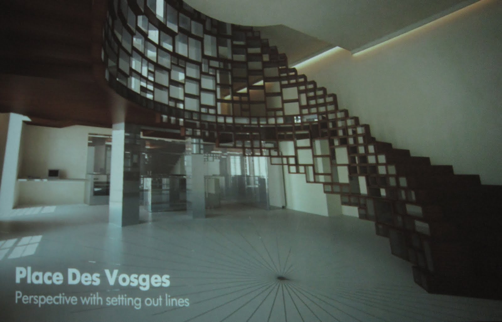
Private apartment, Place des Vosges, Paris 2007, work in progress

Monday, 12 April 2010

Filming Device Analysis

Below is some of the analysis I have produced from one of the films I captured with the filming device (I advise clicking on the image to view it in a larger format):

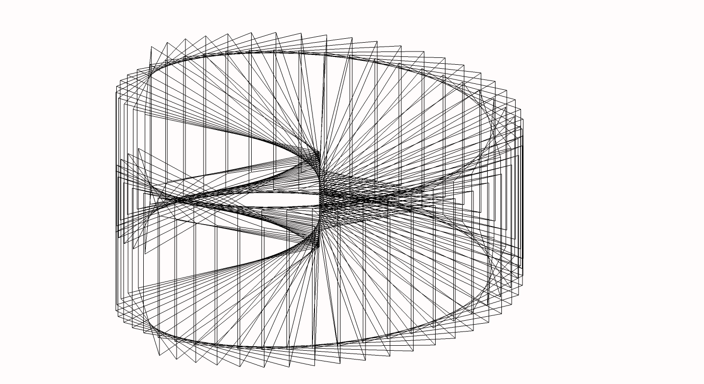
The film lasted 37 seconds and 11 frames. The camera I was using captured 25 frames per second. The montaged images on the right-handside show the entire space captured by the camera, from the start when the camera commenced spinning (when the camera was at the bottom of the space) to the finish when the camera stopped spinning (when the camera was at the top of the stairwell). In total the camera spun through 13.5 loops, I have illustrated the total loop time of each of the rotations graphically in the centre of the page. The graph illustrates that at the start and end of the experiment the loop time was longer, whereas during the middle (majority) of the experiment, the device had built up a fairly regular speed, spinning at a rate of roughly 2 seconds / loop. I have then illustrated a number of points on the graph with lines which radiate out from the point, each one of the lines represents a frame captured during that specific 360 degree rotation, ie. during the first loop, the camera took 6 seconds and 21 frames to complete a full 360 degree rotation, at 25 frames per second this constitutes to 171 frames, therefore I have drawn 171 equally spaced lines radiating out from the central point. On the left-hand side I have illustrated the various heights covered as the camera spiralled up through the space. Along side this I have montaged some of the frames captured at the various heights. These photographs show clearly the effects of the speed of the movement of the camera in blurring the space to various extents.

Tuesday, 6 April 2010

Filming Device Revisited

This post follows on from the previous experiments I was carrying out involving the design of a filming device to capture spiralling looping footage derived from the architecture of the space it is positioned in. Previous designs involved an overcomplicated design which was not capturing the intended footage. Subsequently I have reanalysed the design and scrapped the spiral track which was too complex and would be unrealised for vast height spaces. However these past experiments should not be forgotten.

This next design is much simpler, involving apparatus which can easily be transported and set up in numerous locations.

Apparatus
1 x Rigid 1.5 m timber
1 x Rigid 0.5 m timber
30 m nylon rope
1 x clamp
2 x Screw Eye
1 x M6 Screw & bolts
1 x Camera
1 x plastic tube Ø 1cm (cut into 1cm pieces)

Apparatus

Testing location
Chelsea College of Art & Design Fire Escape stairwell
Storey height 3.6 m (4 levels) > Total Height 14.4 m
Central Void space 2.3 m x 1.15 m

Fire Escape Stairwell

Apparatus Set up
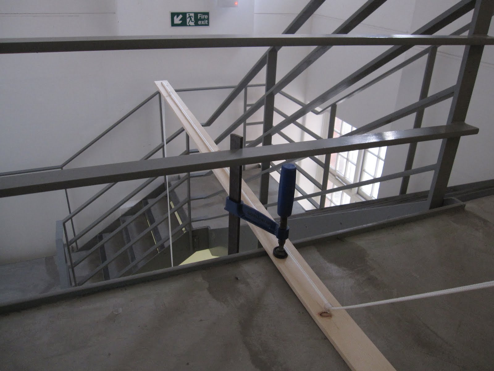
The 1.5 m timber is cantilevered off the highest landing platform in the fire exit, so that the end of the timber is positioned in the centre of the void in plan. The opposite end of the timber is clamped to the landing platform, holding it in place. The plastic tube cuttings were glued to the topside of the timber, to guide the doubled rope which runs through them along the top of the timber and through a hole at the end and thus into the void.

Timber clamped to landing platform with rope running along the topside of the timber and through the hole at the end

Doubled up rope running through the tube pieces along the topside of the clamped cantilevered timber

Each end of the rope is tied to the screw eyes which are attached to each end of the 0.5 m timber. A camera is then attached midway along the 0.5 m timber with a M6 bolt via the tripod attachment and thus the camera hangs upside-down.

Camera is attached midway along the suspended timber

The rope is then fed out fully so that the 0.5 m timber with the camera attached is at the lowest level of the fire exit space.

Camera released to the lowest level of the space

I then went down to the lowest level of the stairwell and rotated the 0.5 m timber in circles to twist the rope above. I then turned the camera on to start the film, ran up to the top level of the stairwell and gradually pulled the rope up, feeding it up through the stairway. As the 0.5 m timber ascends it rotates in circles as the rope untwists and hence the camera films in a continuous spiral up through the space. The footage is upside down, due the way the device holds the camera.

Films captured by the device

Camera Spin 1 from Charlotte Greenleaf on Vimeo.

Screen Shot: Camera Spin 4

I am currently working on some drawings as a way of analysing the footage and the device...

I intend to experiment more with this design, setting it up in a number of different spaces (ideas include lighthouse & woodland)...

I am researching further into the physics of the spinning device involving conservation velocity and absolute and relative motion, in order to try to redesign the device with more and more precision so that the resulting film is more controlled...